A Guide to Static and Cyclic Fatigue Testing of Surgical Fixation Devices in accordance with ASTM F2193
A summary of the standard and the tests involvedStandard At A GlanceMaterials
- Metals
- ASTM F2193
- ASTM F1717
- ASTM F1798
- ASTM F2706-18
- ISO 12189-8
- Flexure
- High Cycle Fatigue
Written by Toby Lane
ASTM F2193 outlines testing of individual metallic screws, plates and rods that are used in spinal implant constructs. Sub-assemblies of these components are tested in accordance with ASTM F1798 (Standard Test Method for Evaluating the Static and Fatigue Properties of Interconnection Mechanisms and Subassemblies Used in Spinal Arthrodesis Implants). The most common standard encountered is ASTM F1717 (Standard Test Methods for Spinal Implant Constructs in a Vertebrectomy Model). ASTM F1717 outlines the testing of the full spinal constructs made up of these components and sub-assemblies.
We recommend that you review the standard fully to understand all of its requirements.
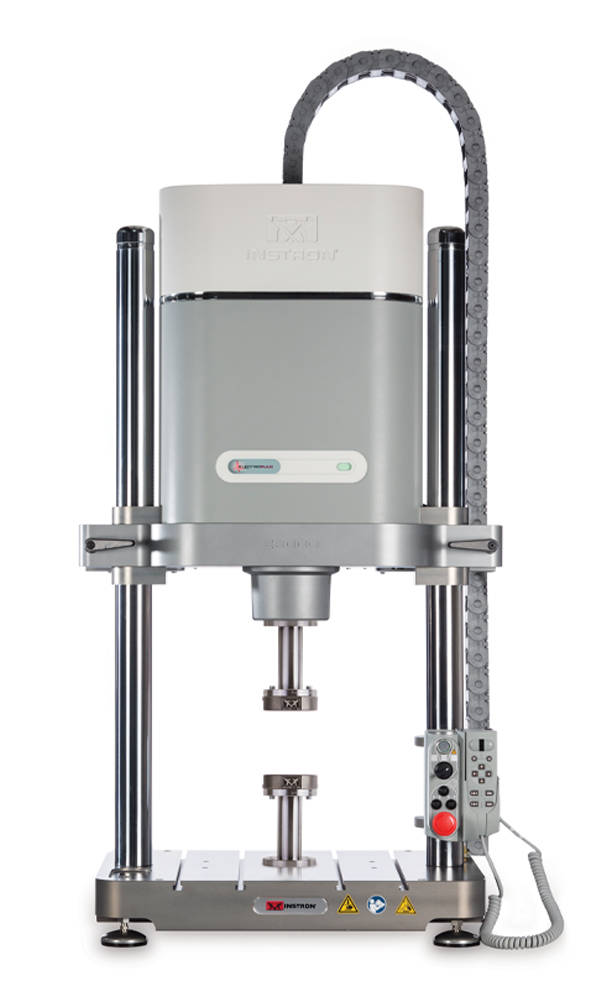
Test SystemBoth the static and fatigue tests can be carried out on a single dynamic test frame such as the ElectroPuls® E3000 or ElectroPuls E10000 All-Electric Dynamic Test Instruments. For customers with Servohydraulic infrastructure, the 8872 and 8874 test frames would also be suitable options for this testing.
Test ParametersBoth Spinal Plates and Rods are tested via the same four-point bending procedure to determine the stiffness, yield moment, ultimate moment and fatigue runout moment at 2,500,000 cycles. Firstly, in both cases, static testing at a displacement rate up to 10 mm/min is carried out for a minimum sample size of 5 specimens.
The fatigue test follows with at least 2 specimens being tested at each load level. Three load levels must be used to provide a minimum of 6 data points. The specimen must not fail after the 2,500,000 cycles for one of these load levels so that the fatigue runout moment can be identified. The load values can be determined by the user or should correspond to 75%, 50% and 25% of the static yield moment.
For the dynamic tests an R ratio of 0.1 is used for thoracic and lumbar components and -1.0 for cervical spine components (to illustrate reverse loading). Testing can be done up to 30 Hz in all cases.


For Spinal Screws, loading is done through cantilever bending. The threaded section of the screw should be imbedded into a 10 mm long synthetic test block that the axial load will be applied to. The head of the screw is then restrained using an anchoring fixture attached to testing system. Typically, screws should have 10 mm of their length embedded into the test block leaving around 5mm of threads exposed between the block and the anchored head. For smaller screws, approximately one-third of the screws entire length should be embedded in the test block. By applying the force in the middle of the test block (5mm from the end of the screw), all screws of a certain length, regardless of diameter, should experience the same acting moment.
The static tests should be carried out with a loading rate no greater than 25 mm/min for a minimum of 5 samples to create load-versus-displacement graphs. The fatigue tests should be completed with a sinusoidal waveform at a maximum of 30 Hz and an R ratio of 0.1 for thoracic and lumber screws. Again, an R ratio of -1.0 should be used for cervical screws. The procedure should then be the same as that of the other two components, with at least 2 specimens being tested at each load level, three load levels being used to create 6 data points, a maximum of 2,500,000 million cycles and 75%, 50% and 25% of the static yield moment acting as starting points for loading values. For all components, testing can be completed in other environments (namely saline solution) with justification and quotation of characteristics such as temperature, pH and solution strengths.
The static tests should be carried out with a loading rate no greater than 25 mm/min for a minimum of 5 samples to create load-versus-displacement graphs. The fatigue tests should be completed with a sinusoidal waveform at a maximum of 30 Hz and an R ratio of 0.1 for thoracic and lumber screws. Again, an R ratio of -1.0 should be used for cervical screws. The procedure should then be the same as that of the other two components, with at least 2 specimens being tested at each load level, three load levels being used to create 6 data points, a maximum of 2,500,000 million cycles and 75%, 50% and 25% of the static yield moment acting as starting points for loading values. For all components, testing can be completed in other environments (namely saline solution) with justification and quotation of characteristics such as temperature, pH and solution strengths.
Related Content