A Guide to Cyclic Fatigue Testing of Artificial Hip Implant Prostheses in accordance with ISO 7206-4, ISO 7206-6, ISO-7206-8 and ASTM F2068

Written by Toby Lane

A SUMMARY OF THE STANDARDS AND THE DYNAMIC TESTS INVOLVEDImplanted metal devices can often experience loosening within the host bone (proximal loosening) as a result of stress shielding. Stress shielding can be described as localized degradation in bone strength due to a decrease in physiological loading of certain areas because of the presence of the stiffer metal implant. As this can occur following even normal activity, Fatigue testing of hip implants is required to understand how abnormal loading profiles can arise and to evaluate endurance properties by simulating the dynamic loading of the implant during gait.

The ISO and ASTM standards have been established to test for both abnormal and normal fatigue loading.
  • ISO 7206-4: Simulates loading when proximal loosening has occurred. Loads are applied through the femoral head of the hip implant to induce compressive, bending and torsional stresses.
  • ISO 7206-6: Examines fatigue of the implant neck, which is more consistent with a correctly fixed implant subjected to normal in vivo loading.
  • ISO 7206-8: Specifies the endurance performance of the implant with the application of torsion.
  • ASTM F2068: “Standard Specification for Femoral Prostheses—Metallic Implants” describes hip implant specifications with reference to the ISO standards.
The Instron® Femoral Fatigue Fixture (CP106632) was designed to meet and exceed the requirements of the ISO tests. The fixture includes a low-friction loading head and adapters for mounting to an ElectroPuls® All-Electric Dynamic Test Instrument. The fixture can also be easily adapted to suit other testing machines and test setups. The flexible specimen holder accommodates a wide variety of hip geometries, offset angles, embedding materials, and embedding depths. Specimens are potted into the holder using an optional embedding fixture to maintain alignment during the potting process. Additionally, the fixture accommodates a small fluid bath for in vivo simulation. WaveMatrix3 software can be used to carry out all of the testing for the ISO and ASTM standards.We recommend that you review the ISO 7206 and ASTM F2068 standards to fully understand the requirements.


Challenges of Hip Implant testing
  • Achieving precise orientation of the specimen in the embedding material due to the specimen geometry.
  • Avoiding heating of specimen due to high frequency testing.
  • Set-up must allow for acceptable compressive, flexural and torsional strain in the specimen.


Hip Implant ISO 7206

Hip Fatigue Fixture

CP106632 Hip Femoral Fixture
Test FixtureThe testing setup outlined by the standards involve embedding of the test specimen into a casting medium using a specified orientation. An axial load is then applied through a device that minimizes the application of off-axis loads on the specimen. The set-up should also accommodate in vivo conditions through incorporation of a fluid bath. The elements listed in the standards include:
  • A lower specimen holder or housing that will contain an embedding medium. The medium used should have a modulus of elasticity between 2000 and 6000 N/mm2 (typically acrylic bone cement or epoxy resin are used).
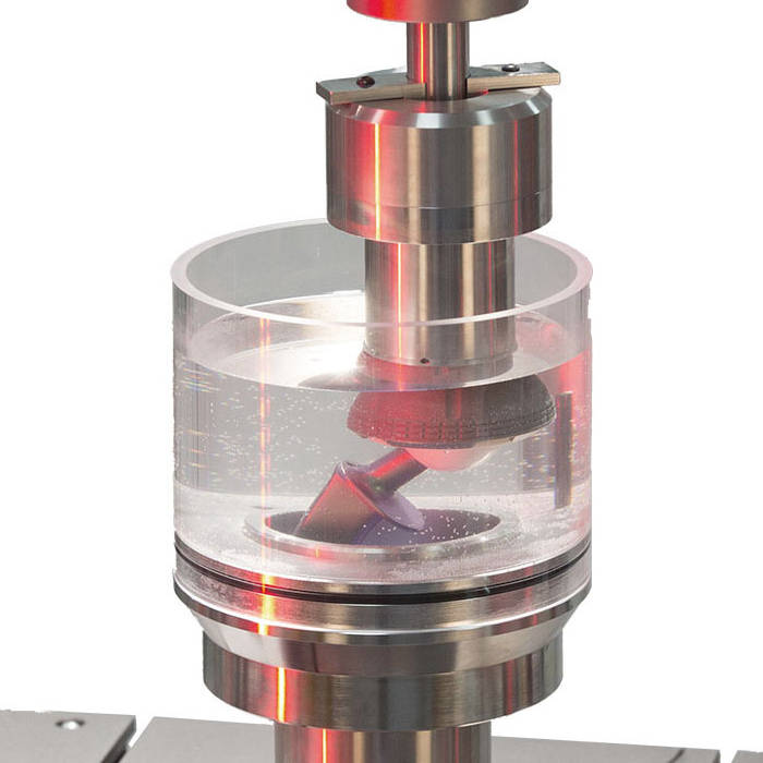
  • A fluid container with temperature control capability, large enough to fully submerge the specimen. Typically, a 0.9 g/l saline solution is used (NaCl + deionized water).
  • A device for gripping the head or neck of the specimen, maintaining the specimen orientation.
  • Adapter for transferring the machine load to the imbedded specimen. The device must feature a lower friction mechanism that is designed to reduce loads that aren’t coincident with the loading axis of the test machine.
Test Fixture 7206-468 Diagram
Test ParametersTo successfully achieve this testing standard, a batch of six identical specimens must withstand 5 million cycles without any signs of mechanical failure. This figure is based on the lower limit of the net stress accumulation seen after 5 years of service life. A value of 10 million cycles is quoted in the ASTM standard and is often used by manufacturers as a more representative figure of a ‘worse-case’ loading regime.

An R ratio of 0.1 is typically used for hip implant testing. As an example, ASTM F2068 suggests testing components between 534N and 5340N.